
DIY Audio Electronics from Octal OTL DIY Tube Headphone Amp
Building the 6DJ8 (ECC88) Tube Headphone Amp This low power tube headphone amplifier is designed along the lines of the Oddwatt power amplifiers, except that this headamp does not require a driver stage. All the circuit gain is in the single output stage.
A headphone amp otl tube design I made (schematic) r/diytubes
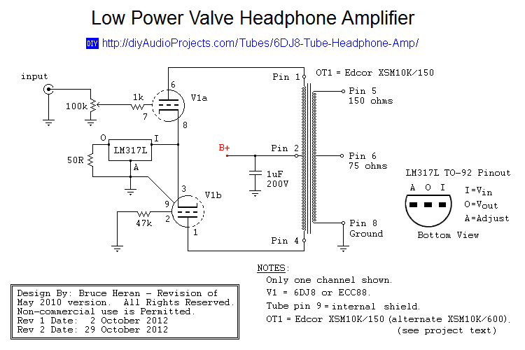
2023-05-19 4:21 pm. #1. Hello, I am releasing a DIY tube amplifier project, the first complete DIY project I've released on this forum. The amplifier is called Aegis. I started my DIY journey on the headphone forum Head-Fi. I have something of a tube DIY blog there where I catalog all of my ongoing projects.

OTL Headphone Amplifier
As a thank you for the 300B amplifier schematics, Stamou has shared his implementation of the 300B single-ended tube amplifier schematic by J.C. Morrison.. The 6DJ8 tube headphone amplifier is suitable for use with many Hi-Fi headphones. Output power is over 100 mW between 32 ohms to 300 ohms. The response is 20 Hz to 28 kHz within 0.5 dB.
The 6DJ8 Headphone Amp Cascade Tubes
Two front panel 1/4″ headphone jacks. Headphone impedance switchable between 30-400 Ohms and 300-4000 Ohms. 2 x 300B Electro-Harmonix output tubes, 2 x 6SL7 Sovtek input tubes, 2 x 5AR4 Ruby rectifier tubes, 2 x OD3 regulator tubes. Frequency Response: 5 Hz to 50 KHz 1dB. Output Power (100 Ohm Headphones): 1W (10 V RMS)

ECC822 Tube OTL headphone amplifier circuit diagram Amplifier_Circuit Circuit Diagram
The tube headphone amplifier schematic typically consists of various components, including transformers, capacitors, resistors, and tubes. These components work together to amplify the incoming audio signals and deliver them to the headphones. The schematics provide a detailed illustration of how these components are connected and the required.
PCL86 Tube Amp
The schematic is shown in Fig. 1. The topology is the same as the hybrid tube/MOSFET line amp. Q1 is a double triode that operates as a differential amplifier, with approximately 2mA in each of the triodes. A constant-current diode D1, which supplies the source current to the differential amp, includes two J508 or E-202 diodes in parallel.

An OTL Tube Headphone Amplifier by Kurt Strain
The schematic for one channel of the headphone amplifier is shown in figure 1. Please see A Top-Level Headphone Amplifier for general information about the circuit. The improvements in this version come from the careful selection of parts, the use of tube diodes, and the elimination of the interstage MKP capacitor.

Diy Tube Headphone Amplifier Schematic Telegraph
The difference between .1% distortion and .01% distortion cannot be heard; a reduction of noise from -60 dB to -80 dB can. If you want to improve the sound of your tube equipment, lower the noise. Of course, low noise and low distortion are not mutually exclusive and it would definitely be better to have both.
Diy Tube Headphone Amplifier Schematic Telegraph
The NS-01 is a small DIY headphone amplifier. It is not the simplest possible project, since it was designed with size and performance in mind. The version presented here should be able to output 90 mA at 7 volts RMS, and work with even low-impedance headphones. To keep the physical size small, the board is designed using surface mount.

P002A EF95 6AK5 Battery Operated Tube Headphone Amplifier EasyEDA open source hardware lab
Tube Amplifiers 2A3 - directly heated power triode SET 2A3 Tube Amplifier Schematic (EF86 input) - [3.5 Watts, SET, class-A] SET 2A3 Tube Amp Schematic by Loftin-White (6SL7 SRPP input) - [3.5 Watts, SET, class-A] 300B - directly heated power triode SET 300B Tube Amplifier Schematic (6SN7 driver) - [8 Watts, SET, class-A] - (Photographs)
All tube headphone amplifier jaeblog
There are not many freely available tube headphone amp schematics using the 12ax7 with the exception of a few electrostatic amps where gain of 1 trilion is necessary. 12au7 and 6dj8 are both FAR more common in headphone amps and there are a bunch of schematics using those tubes over at headwize.

Schematic of Hadphone Amplifier
Schematic 1, (Click here to enlarge.) Ian has been very helpful to me with past tube projects, so I had a good look at that. Eventually, I came up with a schematic, shown small in Schematic 1. You can obtain the schematics for this story by emailing [email protected], with "Curt's schematics, please" in the subject line.

Tube Headphone Amplifier Schematic Typo
This article shows my tube headphone amplifier designs for driving headphones with an impedance of 200 to 600 ohms (I am using these amplifiers with the Sennheiser 580, which has a 300-ohm impedance). The problem with many tube headphone amplifiers is the high output impedance and the low output current that decrease the sonic performance.

Vacuum Tube Headphone Amplifier
Each amp channel draws 25mA and the total filament draw is 1.6A leaving some margin for an indicator light. Here is the schematic for my power supply. The amp circuit only needs between 130v and 150v B+, so there's a fair amount of dropping resistance to get the output voltage into an acceptable range.
Nocturne MKIII Tube Headphone Amplifier Nekolab
In the end, I selected the Texas Instruments TPA6120A2 precision stereo headphone amplifier chip and a pair of Analog Devices AD8610 op-amps as the major active elements of the precision headphone amplifier. The schematic of the amplifier shows the straightforward, symmetrical design with two AD8610s each driving half of the TPA6120A2.

Build a LowVoltage Tube Hybrid Headphone/Line Amp audioXpress
Originally announced in 2010, the Crack is an affordable tube-based headphone amplifier kit offered by the Bottlehead Corporation located in Poulsbo, Washington State, USA. The company was created by the 'President for Life' Dan 'Doc B' Schmalle in the mid-1990s, and primarily offers DIY tube audio kits for both headphones and home stereos.